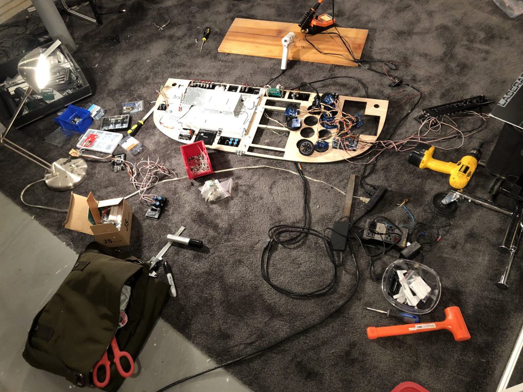
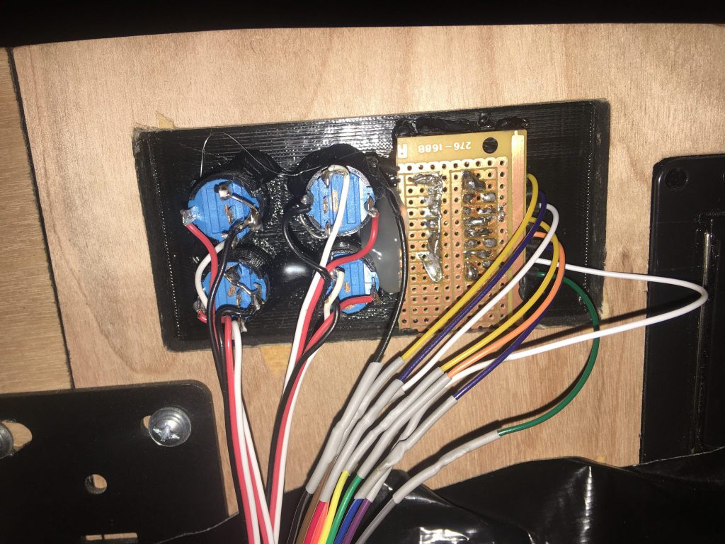
I’ve taken the last couple days of down-time to study up on using the wonderful app, Fritzing, to help me design custom interface circuit boards for better back panel connections. Although the front of the sim looks pretty great right now, the back is a spaghetti mess of wires and dodgy soldered connections. Here’s a pretty good glimpse of the big connection day, which sums it all up. What a mess, who works like this!? Me.

It has become too easy for wires to pop off randomly, probably due to the motion seat and constant motion with no strain relief on the wires. Lesson learned, as it takes me at least an hour to figure out what broke each time. At the time of the last build, I didn’t realize the benefit of easy connections and interchangeable parts, but now that I’m getting better at designing custom boards, this shouldn’t be too bad, I hope.
Fabrication with the 3D printer, CNC or laser cutter has been a tedious iterative process. I have found myself spending much more time building this thing than flying it. I do love the process though, it’s fun, challenging and has given me the confidence to continue to improve the sim over time.
It’s time to turn this mess into a nice PCB!

I plan to create a master interface board which will mount 2 or 3 Arduino Mega 2560’s with with a few GPIO connectors, which will be split off to connect all of the individual panels. Once I have that, I’ll re-design all of the laser cut back-panels of the instruments and switch panels with custom boards which will have the switches and LEDs mounted. I already have the Fusion 360 files for the panels, hopefully these should translate well to the circuit design so I don’t have to recut any original panels.
