I recently taught myself how to use Autodesk Eagle in order to create custom panel electronics with a much more professional look and to keep things working. It’s taken me about a year on and off to learn it, but having recently made my first few successful PCBs, I’m really happy I invested the time in it.
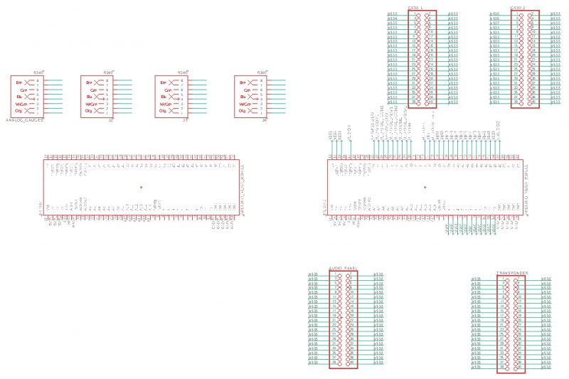
I’m just getting started designing a main breakout panel, sort of the brains of main panel. Once this is complete, I’ll build each mini-panel and connect them through GPIO 40 pin & RJ-45 8 pin connectors. This will be a much more organized way of routing batches of cables and easier to adjust cable lengths. The basic schematic is below, but needs a ton of work. Eagle has a cool feature which virtually connects wires through ‘nets’ which avoids the mass amount of wires criss-crossing in your schematic.