
The goal of this tutorial is to teach you how to modify your ArdsimX Arduino code for 3rd party libraries and utilize somewhat more external electronics in your sim. Our task here is to add an LED bar graph trim tab to work with X-Plane 11 to show us where the trim elevator is currently set. I set up my stick thumb control for trim nose up and nose down, but you can use the virtual control on your aircraft as well.
When I built the original version for my sim, I did it the hard way, by individually wiring up each LED to a digital output of one of the Arduino Megas. Mostly, because I didn’t want to take the time to figure this out. But now that it all works, I’m working to improve the sim one step at a time. Real compared to sim version, below. I added this to my sim to match the Diamond DA20 trainer.
Step 1: Gather Materials
(1x) Arduino Uno
(1x) LED bar graph module
On Amazon and Ebay, I found a few different LED bar graphs, some multi-colored. I used solid red module, to match the DA20. The modules are simple to use with an LED controller built onto the board. It only uses 2 pins for control, one for clock and one signal pin.
Step 2: Wire up your parts
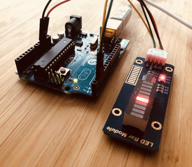
Connect the LED as normal to the Arduino. Connect outer pins to GND and +5V and the center pin to one of the analog inputs, I’m using Analog Input #1 (A1). Here’s a picture of my setup. <BR>
Step 3: Find Dataref and write your config file.
I found the Dataref using the Configurator. No need to jump into the Dataref viewer for this one. I’m using sim/cockpit2/controls/elevator_trim. The data.cfg file is very basic. In the Output [O] section, we are sending the dataref signal out.
————-Copy code below and save as data.cfg in your ArdsimX Plugin Folder——————–
@ ================= INFO =================

Board #1 - Arduino (USB) -------------------------------------------------------

---- Digital pins: ----

1 - Elevator Trim

@ ================= CONFIG =================

*1-1Ui

[O]
1 3 sim/cockpit2/controls/elevator_trim
What’s happening under the hood:
[O]
1 3 sim/cockpit2/controls/elevator_trim
- 1 = The ID of the output, used by the ArdsimX Arduino code to register which output. This has nothing to do with the pin number. Once you get used to this, it’s pretty easy to read.
- 3 = Indicates that we’re sending a float. A ‘1’ would indicate that we’re sending a Boolean value, for reference.
- And sim/cockpit2/controls/elevator_trim is the [val] variable we’re sending on ID 1. This will make more sense in the next section, when we review the Arduino code.
Step 4: Upload your Ardsimx code to your Uno.
————-Copy Code in your Arduino IDE and Upload onto your Arduino——————–
#include <Adeept_Bar.h>
Adeept_Bar bar(3, 2);  // Clock pin, Data pin


//================================
#include <ArdSimX.h>          //  -- ArdSimX library
//================================


//------------------------------------------
void setup()  {
    BoardNumber 1;            // -- Assign Board Number here  (0...9)

    bar.begin();             // initialize
    // Turn on all LEDs, just a confidence test of LED Bar
    bar.setBits(0x3ff);
    delay(1000);
}

//------------------------------------------
void loop()   {
     ArdSimScan;               // main loop  - scan inputs and read incoming data for output
}


void ProgOut(byte id, float val) {
   if (id==1) {   // here is your custom code or function call
      if (val < -.201)                bar.setBits(0b000000000000001);
      if (val < -.151 && val > -.2)   bar.setBits(0b000000000000010);
      if (val < -.101 && val > -.15)  bar.setBits(0b000000000000100);
      if (val < -.051 && val > -.1)   bar.setBits(0b000000000001000);
      if (val < 0 && val > -.05)      bar.setBits(0b000000000010000);
      if (val > 0 && val < .05)       bar.setBits(0b000000000100000);
      if (val > .051 && val < .1)     bar.setBits(0b000000001000000);
      if (val > .101 && val < .15)    bar.setBits(0b000000010000000);
      if (val > .151 && val < .2)     bar.setBits(0b000000100000000);
      if (val > .201)                 bar.setBits(0b000001000000000);
   }
}
The lines below add the Adeept_Bar library to the ArdsimX standard sketch. This enhances to abilities of ArdsimX to utilize 3rd party libraries and hardware. Pins 2 & 3 are used to communicate with the LED bar.
#include <Adeept_Bar.h>
Adeept_Bar bar(3, 2);  // Clock pin, Data pin
I commented out the use of ethernet as my Arduino UNO is connected via USB. Otherwise, just added these lines to the setup, which the LED bar needs. I pulled this from the example code which came with the LED module.
    bar.begin();             // initialize
    // Turn on all LEDs, just a confidence test of LED Bar
    bar.setBits(0x3ff);
    delay(1000);
Here’s the meat of the the addition. Anytime you want to send custom data to or from your Arduino, you need to add it into the void ProgOut(byte id, float val) function. This took me awhile to get the hang of, but it’s pretty simple. Try not to overcomplicate it for yourself.
void ProgOut(byte id, float val) {
   if (id==1) {   // here is your custom code or function call
      if (val < -.201)                bar.setBits(0b000000000000001);
      if (val < -.151 && val > -.2)   bar.setBits(0b000000000000010);
      if (val < -.101 && val > -.15)  bar.setBits(0b000000000000100);
      if (val < -.051 && val > -.1)   bar.setBits(0b000000000001000);
      if (val < 0 && val > -.05)      bar.setBits(0b000000000010000);
      if (val > 0 && val < .05)       bar.setBits(0b000000000100000);
      if (val > .051 && val < .1)     bar.setBits(0b000000001000000);
      if (val > .101 && val < .15)    bar.setBits(0b000000010000000);
      if (val > .151 && val < .2)     bar.setBits(0b000000100000000);
      if (val > .201)                 bar.setBits(0b000001000000000);
   }
}
There are two variables, id and val. From your data.cfg file,ID refers to this line.
1 3 sim/cockpit2/controls/elevator_trim
When ID=1, Val will equal whatever value is coming from the Dataref for elevator_trim. Here’ I’m using If statements to filter the value. For example, this line will set the center LED to glow, representing the Trim in the neutral position. if (val < 0 && val > -.05) bar.setBits(0b000000000010000);
Step 5: Taking This Further
Now that you’ve had some experience modifying the basic Arduino code for ArdsimX, try other hardware and software libraries. There are many off-the-shelf hardware components ready to be used with flight simulators that will be much easier now to use with ArdsimX. I would love to hear what you came up with. Please post a comment if you have any trouble making this work. .